
Microwave Optical Terminal Equipment
Analog Optical Communication · IF to 67 GHz · Hot‑swappable · Remote Control
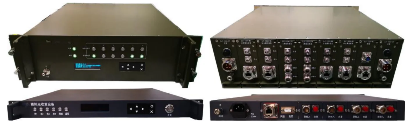
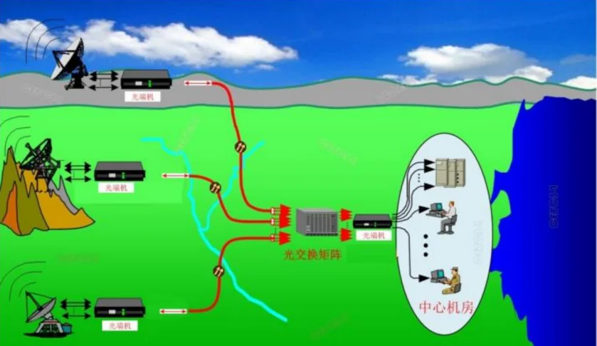
Our high-performance microwave optical terminal equipment provides transparent RF communication and analog optical transmission support across ultra-wide frequency bands. As an experienced original equipment manufacturer and global subsystem supplier, Chengdu Microwave builds these rugged fiber platforms on a modular 1U/2U/3U line-card structure. Designed to integrate smoothly with advanced solid state power amplifier networks, wideband receiver blocks, and microwave power amplifier subsystems, this card-insertion architecture handles up to 8 channels with real‑time optical power detection and intelligent remote control network management – serving as an ideal long-distance replacement for heavy, lossy coaxial networks.
Functional Requirements (All Models)
- Power failure memory and power‑on recovery functionality
- Front panel optical signal status/alarm indicators
- Input power monitoring and saturation alarm indicators
- Panel with configurable network parameters (serial port, Ethernet, IP address)
- Panel‑based configuration of operational parameters (gain)
- Query response functions for equipment model/serial number or unique identifier
- Comprehensive remote monitoring and query capabilities
- Remote control functionality for operational parameters (gain)
- Adaptive transmission distance capability
- Optional Gigabit Ethernet optical transmission channel
- Hot‑swappable service modules (1U/2U/3U line-card structure)
Review our standard single-band microwave optical terminal equipment matrix below. We fully support customized channel distribution limits, specialized rf power amplifier integration parameters, and custom frequency band adaptations to align with your integrated network. Contact our engineering team directly for official technical datasheets and competitive factory-direct quotes.
| SKU | Frequency Range | Wavelength (nm) | Input P1dB | In‑band Flatness | Noise Figure | Range (km) |
|---|---|---|---|---|---|---|
| MCW-IF | 10 – 150 MHz | 1310/1550 | ≥ -10 dBm | ±0.5 dB | ≤15 dB | 0–30 |
| MCW-0330A | 30 MHz – 3 GHz | 1550 | ≥ -10 dBm | ≤2 dB | ≤15 dB | 0–20 |
| MCW-3442A | 3.4 – 4.2 GHz | 1310/1550 | ≥ -10 dBm | ≤±1 dB | ≤20 dB | 0–30 |
| MCW-7G9G | 7 – 9 GHz | 1310/1550 | ≥0 dBm | ≤±1 dB | ≤18 dB | 0–30 |
| MCW-10G13G | 10.7 – 12.75 GHz | 1310/1550 | ≥ -10 dBm | ≤±1.5 dB | ≤23 dB | 0–30 |
| MCW-0842A | 800 MHz – 4.2 GHz | 1550 | ≥ -10 dBm | ≤±2 dB | ≤18 dB | 0–20 |
| MCW-3090A | 3 – 9 GHz | 1310/1550 | ≥ -15 dBm | ≤±2 dB | ≤15/8 dB | 0–20 |
Our multi-band analog link cards enable coherent wideband fiber tracking for composite rf amplifier and telemetry architectures. Custom configuration adjustments for dedicated sub-bands or specific input power tolerances can be executed upon engineering review. Request standard factory pricing data below.
| SKU | Frequency Range | Flatness | Input P1dB | Noise Figure | VSWR | RF Connector |
|---|---|---|---|---|---|---|
| MCW-2G8G | 2 – 8 GHz | ±2 dB | ≥ -18 dBm | ≤20 dB | ≤1.8:1 | SMA |
| MCW-7G14G | 7 – 14 GHz | ±2 dB | ≥ -18 dBm | ≤20 dB | ≤2:1 | SMA |
| MCW-2G18G | 2 – 18 GHz | ±3 dB | ≥ -20 dBm | 40 dB @20GHz | ≤2:1 | SMA |
| MCW-50M40G | 50 MHz – 40 GHz | ±5 dB | ≥ 13 dBm | 46 dB @40GHz | ≤3:1 | K (2.92mm) |
Explore expanded high-frequency millimeter-wave and sub-band optical transmission lines. These modules are modularly compatible with industry-standard test instruments, wideband receivers, and radar distribution lines. Full technical parameter datasheets are available upon request.
| SKU | Frequency Range | Noise Figure | Flatness | VSWR | Notes |
|---|---|---|---|---|---|
| MCW-30M1500M | 30 MHz – 1500 MHz | 15 dB | ≤±1 dB | 1.5:1 | P1dB adj -15~+15dBm, att 0-25dB |
| MCW-L | 950 MHz – 2150 MHz | 15 dB | ≤±1 dB | 1.5:1 | L‑band |
| MCW-2042A | 2 – 4.2 GHz | 18 dB | ≤±1 dB | 1.6:1 | S/C band |
| MCW-4G8G | 4 – 8 GHz | 20 dB | ≤±1.5 dB | 1.8:1 | C‑band |
| MCW-7G10G | 7 – 10 GHz | 23 dB | ≤±1.5 dB | 1.8:1 | X‑band |
| MCW-Ku | 8 – 12.5 GHz | 20 dB | ≤±1.5 dB | 2:1 | Ku‑band |
| MCW-12G18G | 12 – 18 GHz | 28 dB | ≤±2 dB | 2:1 | ≥ -15dBm P1dB |
| MCW-26G32G | 26 – 32 GHz | 28 dB | ≤±1.5 dB | 2.5:1 | ≥ -20dBm P1dB |
| MCW-26G40G | 26 – 40 GHz | 30 dB | ≤±3 dB | 3:1 | ≥ -20dBm P1dB |
| MCW-0167A | 100 MHz – 67 GHz | 52 dB | ≤±7 dB | 3:1 | ≥ 15dBm P1dB |
All models share the common functional requirements listed above. Customization (frequency, gain, connectors) available upon request.